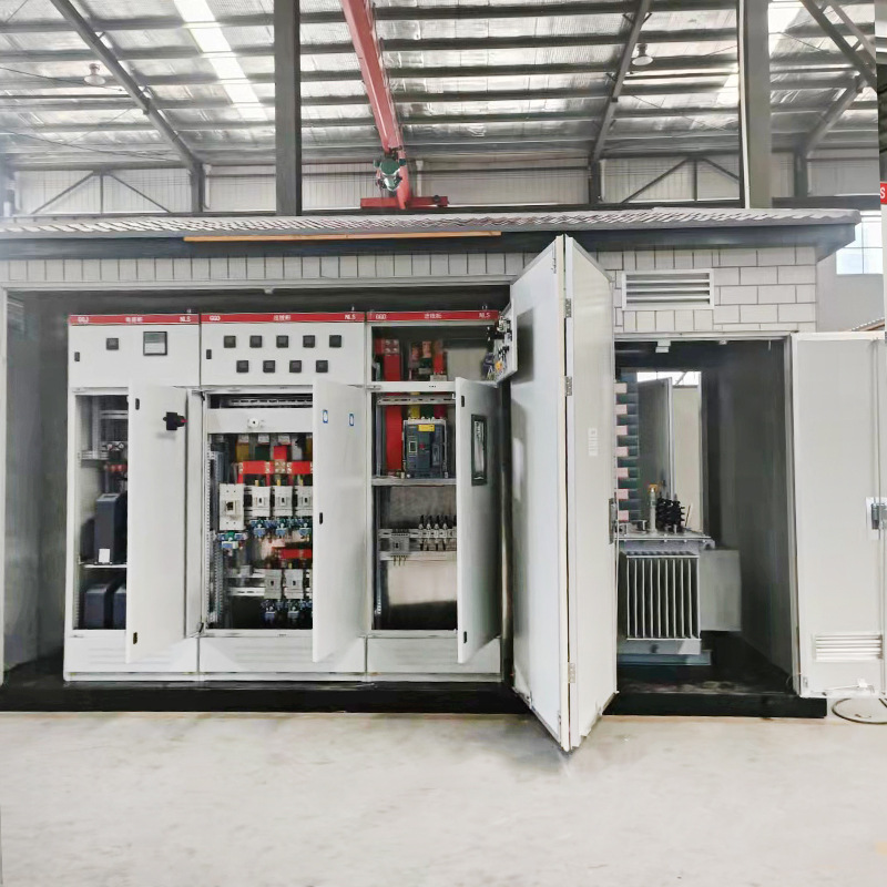
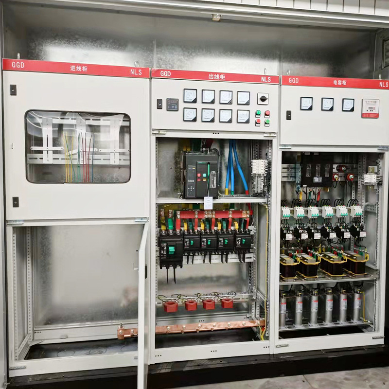
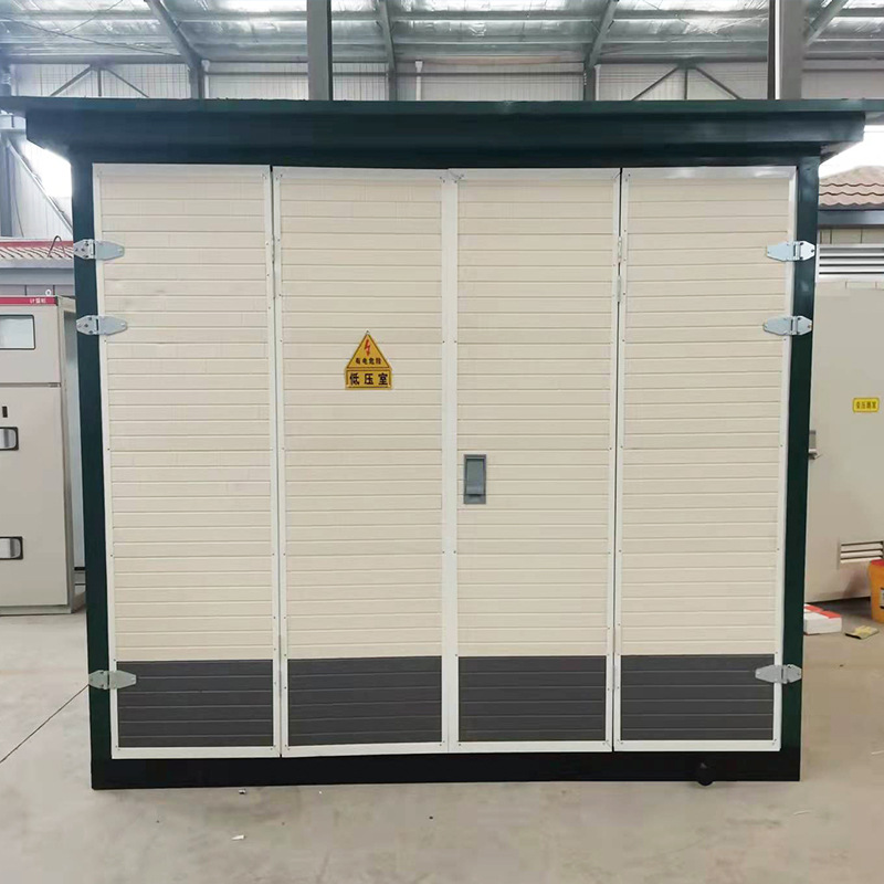
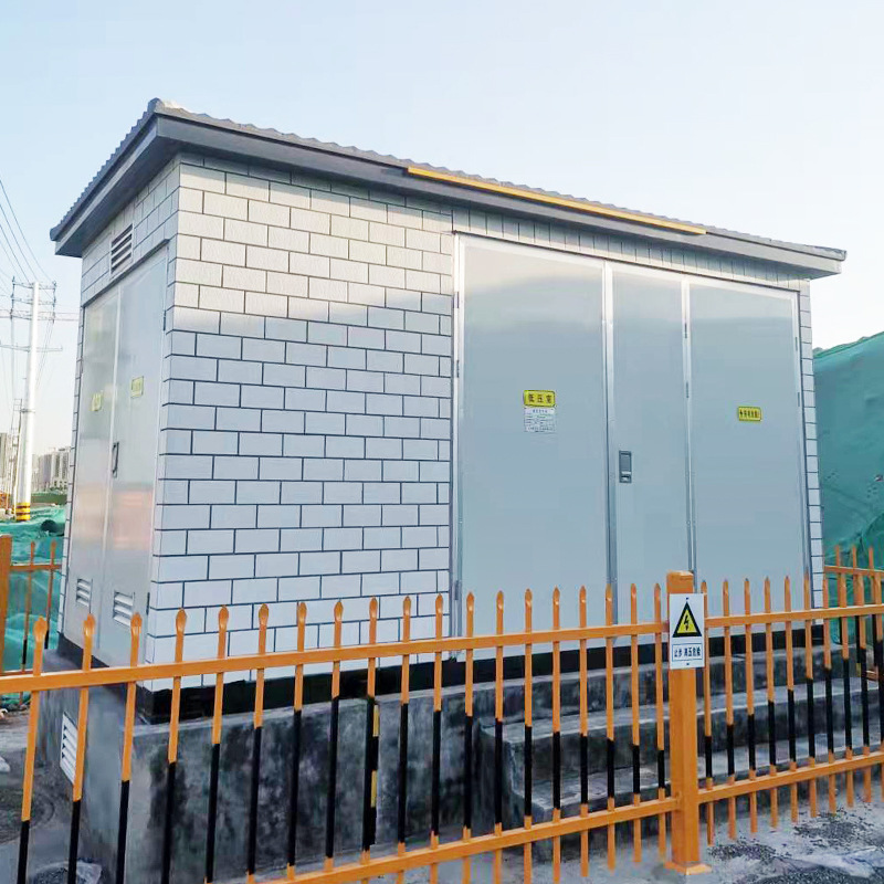
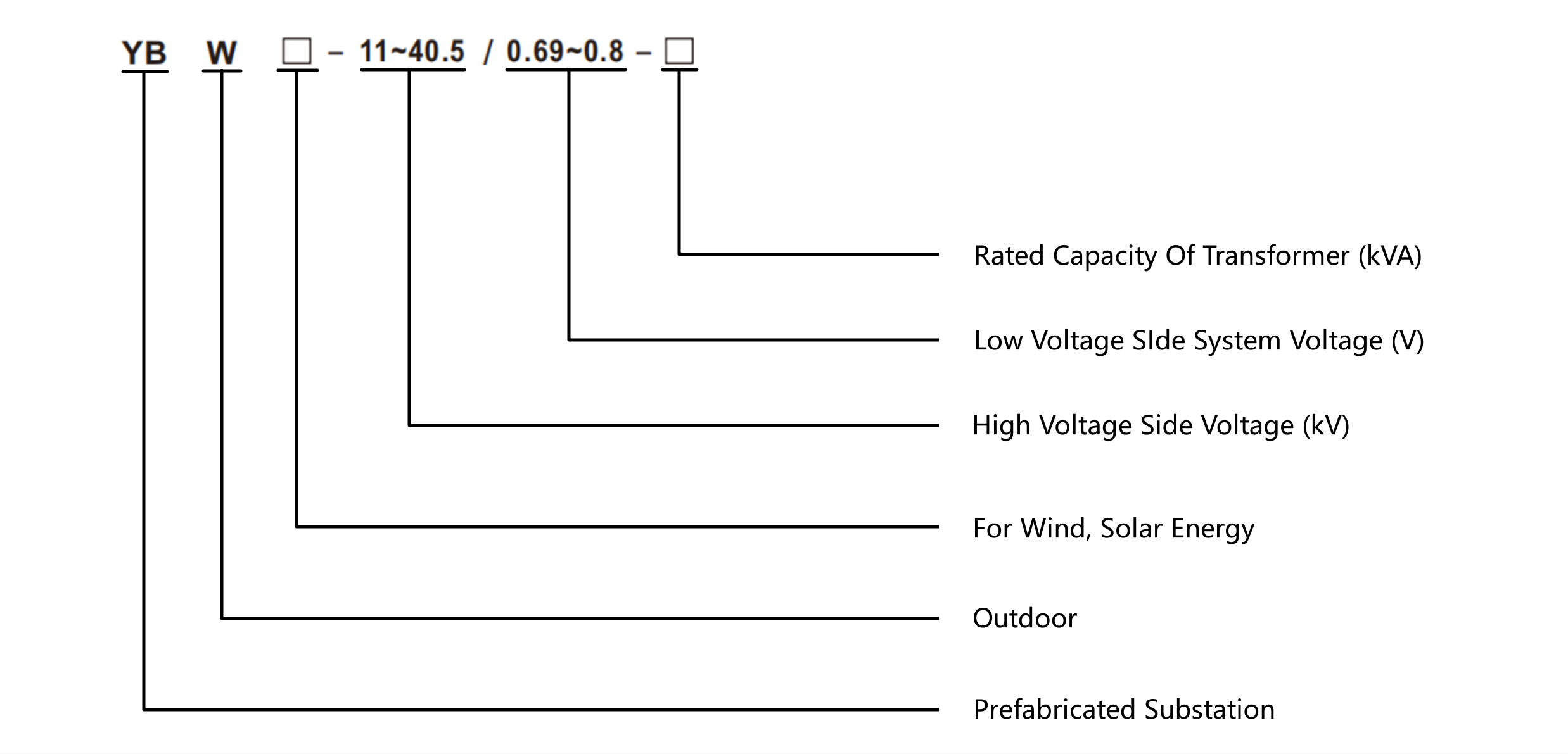
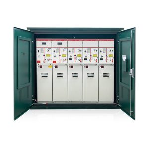
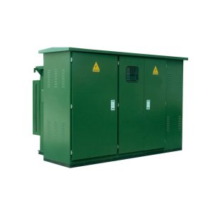
YBW Series Outdoor prefabricated substation (For wind, solar energy)

Category

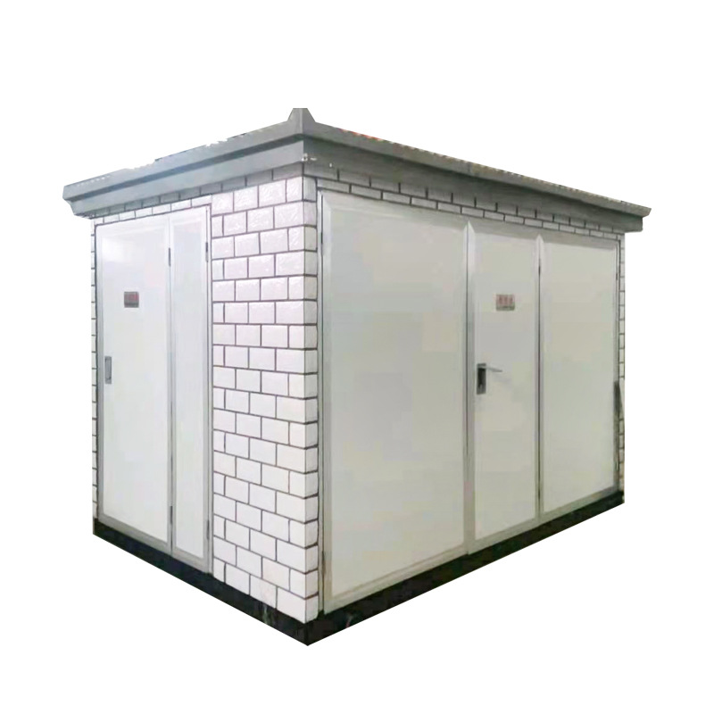
YBW-40.5/12 Prefabricated substation

This Prefabricated substation are used for the higher voltage 40.5 kV, the lower voltage 12 kV three-phase AC 50 hz outdoor equipment.

And widely be used to cities, towns, factories and oil field etc. Also be applied to some large construction sites, transformation and distribution of electrical energy.

Depending on complete sets of strong, it can cover some small areas, easy installation and used with the advantage of low cost, high degree of automation, safe and reliable running etc.

Product Highlights
  • Standards : IEC 1330
  • Compact design
  • Easy operation and installation
  • Reliable interlock
  • Less Maintenance

Overview

Currently, the global energy crunch and the growing emphasis on environmental protection have made the improvement of energy efficiency and the development of renewable energy sources two key aspects of sustainable energy development. Renewable energy sources, such as wind and solar energy, are receiving increasing attention and are considered to be the most promising avenue for the large-scale development and application of “green energy”.

In China, in order to transmit electricity over long distances, the export voltage of wind or photovoltaic (PV) generating units needs to be boosted to 690 V. Typically, cables are used to connect the generators to specialized box-type step-up transformers. These transformers step up the voltage to 40.5 kV or 12 kV, which is then transmitted to the central substation of the wind or PV farm. The voltage is then further boosted and the power is fed into the grid.

Therefore, our company designs and develops 40.5 kV and 12 kV wind power step-up transformers and photovoltaic step-up transformers to meet these requirements and to achieve optimum performance.

YBW Series Outdoor prefabricated substation

Working Conditions
  1. Altitude not exceeding 1000 meters.
  2. Ambient temperature not more than + 50 degrees Celsius and not less than -25 degrees Celsius.
  3. Relative humidity: Average daily humidity not exceeding 95%, average monthly humidity not exceeding 90%,
  4. Monthly average humidity not exceeding 90%, monthly average humidity not exceeding 90%. Outdoor wind speed does not exceed 35 meters per second.
  5. No fire and explosion hazards, serious pollution, chemical corrosion, or severe vibration at the installation site. A small amount of dust, smoke, salt spray and corrosive gas pollution,
  6. A small amount of dust, smoke, salt spray and corrosive gas pollution is allowed, and the degree of pollution does not exceed Grade II.
  7. Seismic intensity: VII degree;
  8. Horizontal ground acceleration ≤ 0.2m/s; vertical acceleration less than 0.1m/s, safety factor 1.67.

Note: In the special use of the environment, when the use of the place beyond the requirements of the normal use of environmental conditions, the user needs to consult with the manufacturer.

Technical Parameters

Technical parameter

No. Items Unit Parameters
1 Rated frequency Hz 50~60
2 System voltage KV 11, 13.8, 15 30, 33, 36
3 Maximum operating voltage KV 15 40.5
4 Rated current of switch A 630, 1250, 1600, 2000, 2500
5 Switch transfer current A 1000~3150
6 Rated short-time withstand current KA 12.5 (2s or 4s), 16 (2s or 4s), 20 (2s or 4s)
7 Rated peak withstand current KA 25,31.5, 40
8 Power frequency withstand voltage (ground and phase-to-phase isolation fracture) KV 42/48 95/115
9 Lightning impulse withstand voltage (ground and phase-to-phase isolation fracture) KV 75/85 185/215
10 Rated short circuit breaking current (current limiting fuse) KA 31.5
11 Capacity of no-load   transformer KVA 1000~20000

Installation

Product acceptance, installation and commissioning
  1. Users are advised to carefully inspect the received goods in accordance with applicable regulations. In the case of immediate installation, the items should be stored in suitable locations that conform to normal usage conditions. Additionally, it is important to ensure the proper preservation of the box transformer.
  2. The foundation of installation shall be made in strict accordance with the foundation drawing provided by the manufacturer or jointly formulated by both parties.
  3. Theinstallation site shall have sufficient loading and unloading space, and the unloading shall also run according to the loading requirements.
    The installation foundation should be constructed strictly according to the manufacturer’s provided foundation drawing or a mutually formulated plan. Sufficient space should be available at the installation site for loading and unloading equipment, and the unloading process should adhere to the specified loading requirements.
  4. The gap between the base and the foundation of the box transformer shall be sealed with cement mortar to prevent rainwater from entering the cable room.
  5. To prevent rainwater from infiltrating the cable room, it is imperative to seal the gap between the base and the foundation of the box transformer using cement mortar. This will effectively create a barrier, safeguarding the cable room against water ingress

Ordering Instructions

Users should provide the following data to our company when ordering:
  1. Product name, model, quantity and delivery date;
  2. Material and color of box change shell;
  3. Primary system diagram and technical specification of box transformer;
  4. We are responsible for the installation and debugging of the components provided by the user or please explain in advance if we need to reserve positions;
  5. Consult with the manufacturer for special requirements (e.g. ambient temperature exceeding standard, operating corridor or maintenance channel size).

Have you
Any Questions?

Can’t find an answer to your question, or want more information about our products? If so, please feel free to get in touch with our professional team. We’re here to help you drive your projects to success.

Contact us for a quotation