FAQ
1. What does an ATS do, and how does it work?
An ATS continuously monitors the voltage and frequency of the primary power source. When the ATS detects abnormal conditions—such as outage, undervoltage, overvoltage, or phase failure—it automatically disconnects the faulty source and transfers the load to the backup supply.
When the main supply becomes stable again, the ATS can automatically re-transfer the system back to its normal operating state. The core objective is to guarantee uninterrupted power for sensitive or critical loads.
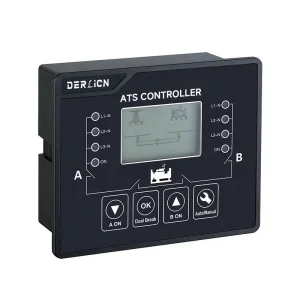
2. What are the differences between switch-based ATS (PC class) and breaker-based ATS (CB class)?
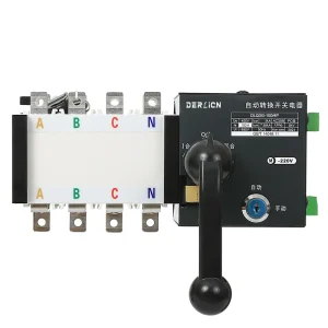
A switch-based ATS uses load-break switches and does not include overcurrent or short-circuit protection inside the device. These units rely on upstream circuit breakers and are typically used when the electrical system already includes adequate protection.
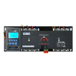
Breaker-based ATS devices, however, utilize molded case circuit breakers (MCCBs) or air circuit breakers (ACBs) and provide direct protection against overloads and short circuits. These are preferred for heavy-duty or mission-critical environments such as hospitals, manufacturing plants, and data centers.
Choosing between them depends on your system protection design, available fault current, and safety requirements.
3. What type of applications typically require an ATS?
ATS devices are used across a wide range of sectors.
They are common in residential backup systems with generators, commercial buildings, industrial facilities, telecom towers, medical centers, and water treatment plants.
In high-reliability environments—data centers, airports, emergency lighting systems, and fire-fighting pumps—an ATS is essential to ensure continuous power to critical loads.
4. What is the difference between a switch-based ATS (PC class) and a breaker-based ATS (CB class)?
There are two main types of ATS devices.
A switch-based ATS uses load-break switches and does not include overcurrent or short-circuit protection. It must be used together with upstream protective devices and is ideal for standard residential or commercial systems where protection is already provided elsewhere.
A breaker-based ATS uses molded case circuit breakers (MCCBs), which provide built-in protection against overloads and short circuits. This type is preferred in critical applications such as hospitals, data centers, or large industrial systems, where higher safety and fault-handling capacity are required.
5. Does an ATS provide any protection on its own?
Only breaker-based models provide direct protection. Switch-based models serve only as transfer devices and therefore need proper upstream protection.
This distinction is important because many customers mistakenly assume that the ATS itself replaces circuit breakers; in most installations, it does not.
6. What transfer time can I expect?
Transfer time depends on the ATS type and the condition of the power sources. In general, switch-based units transfer within approximately 0.3 to 1.5 seconds, while breaker-based units typically fall within 0.5 to 2 seconds. For generators, a delay may be added to allow the generator to stabilize before load transfer. Some systems allow fully adjustable delays, ensuring compatibility with various types of power sources.
7. Can the ATS be used with generators or renewable energy systems?
Yes. ATS units are compatible with:
Diesel and gasoline generators
Solar inverter systems
Battery energy storage systems
Hybrid power plants
When used with generators, the ATS can automatically send a start command and only transfer load when generator voltage is stable. Parameters can be customized based on your generator controller.
8. What is the lifespan of an ATS?
The lifespan depends on mechanical endurance, electrical endurance, and operating environment.
Our ATS systems are designed for:
- High mechanical life (tens of thousands of operations)
- Long electrical endurance under rated load
- Stable performance under high operating temperaturesWith proper maintenance and installation in a clean, dry environment, ATS devices typically remain reliable for many years.
9. How do I select the correct ATS rating?
The most important factors to consider are the load current, system voltage, and short-circuit level of your installation. You should also determine whether you need built-in protection, what type of transfer logic you prefer (automatic, delayed, or manual), and whether the application is residential, commercial, or industrial. Providing these details allows us to recommend the appropriate model and configuration.
10. What certifications do your ATS units comply with?
Our ATS series is designed and tested according to IEC 60947-6-1, and models can be supplied with CE, RoHS, and other international certifications depending on project requirements. Compliance documents are available upon request.
11. Is the installation process complicated?
Installation should always be performed by a qualified electrician. The ATS must be wired according to the correct phase sequence, properly grounded, and installed with suitable protective devices if using a PC-class model. Adequate ventilation and spacing are also important to ensure stable operation. We provide detailed wiring diagrams and installation manuals for each model.
12. What if the ATS fails to transfer?
Common causes include:
- Incorrect wiring
- Insufficient voltage at backup source
- Mechanical obstruction
- Faulty control signal
- Loose terminals
We provide detailed troubleshooting guidelines in our manuals, and our technical support team can assist in identifying the issue.
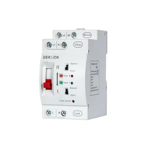
13. Do you offer remote monitoring or smart features?
Yes. Depending on the model, ATS units can support RS485/Modbus communication, WiFi or LAN monitoring, and real-time status reporting. These functions are useful where centralized management or integration with building automation systems is required.
14. Where can ATS devices be used?
ATS solutions are widely used in residential buildings, commercial facilities, industrial plants, data centers, telecom stations, hospitals, and anywhere that requires an uninterrupted electrical supply. Whether the load is critical or general-purpose, an ATS provides added reliability and operational safety.
15. Is the ATS compatible with my existing electrical system?
ATS units are compatible with most distribution systems, including TT, TN-S, TN-C-S, and IT networks.
To ensure compatibility, we typically ask customers to confirm:
- Line voltage and frequency
- Neutral treatment method
- Fault level / short-circuit current
- System grounding method
- Generator type (if used)
Based on this information, we can recommend the correct model and configuration.
16. Do you provide spare parts, accessories, and OEM customization?
Yes. We support OEM/ODM customization, including branding, special control logic, non-standard voltages, and customized enclosures.
And we also offer:
- Spare auxiliary contacts
- Control modules
- Mechanical interlocks
- Breaker accessories (for CB-class)
- Customized logic and enclosures
If you have project-specific requirements, feel free to share them with us.
17. What is the warranty and after-sales support?
Standard warranty is 12 months, with optional extended warranty plans for project-based customers. We provide:
- Technical support
- Installation guidance
- Wiring diagrams
- Troubleshooting assistance
- Replacement parts if necessary
Our goal is to ensure long-term reliability and customer satisfaction.